Broadcast Television
|
[Diagram showing scanning beam
of television forming picture.]
|
| [61] How
Scanning Works. |
No one person is responsible for the invention of television;
it was developed by incremental improvements from the 1880s to the 1930s, when a workable television set was first made available
to the public. A traditional video camera scans a picture and converts it to a beam of electrons that varies in darkness and
lightness with the intensity of the image. In the United States, the [63] standard television image has historically consisted of 525 lines scanned 30 times per second. The
television set then receives the electronic signal, and converts it back into an image by projecting the beam, 525 lines,
30 times per second, across the picture tube. For color television, the beam is broken down into three component parts, which
make up the primary colors from which all the other colors may be reproduced.
|
[62] Pioneers of radio and television.
Guglielmo
Marconi, the father of wireless communication (right) with David Sarnoff (left), a major promoter of radio and television.
Sarnoff began his career as a wireless operator. He gained national attention when, for seventy-two hours, he relayed the
names of Titanic survivors rescued
by the Carpathian. As an employee of the American Marconi Company, Sarnoff developed
plans for a “radio music box.” At the time, most people dismissed his proposals. Later, Sarnoff became an executive,
and eventually president, of the Radio Corporation of America, which acquired the assets of American Marconi. Sarnoff oversaw
the establishment of the National Broadcasting Company. |

|
|

|
|
By post-Depression standards, $600 was a lot of
money; a new Ford four-door sedan could be bought for about the same price. |
The miracle part of this process was not just in capturing or reproducing images, but in delivering images to locations
far removed from the source. This was the technology of radio—wireless communication—first developed by Guglielmo
Marconi in 1895. Because of the intervening depression and World War II, however, it was not until the 1950s that commercial
television really caught on. This new technology allowed millions of viewers to see programs from just about anywhere in the
country, using their own receivers in the comfort of their own living rooms. People didn’t have to go to the movies;
the movies came to them.
Victor G.Barker A.M.I.R.E.E. Aust J.P. Takes you through the early years
of television broadcasting in the United Kingdom.
E.M.I. How original
You are about to turn back the calendar to 1936 on a cold winters day at
Alexandra Palace, London.
Standing alone in a corridor leading to the "Baird studio"
was the man himself John Logie Baird a Scotsman held in high esteem by the British public as the inventor of "television"
, the word itself is rather a strange adjective being formed from two words of different languages "Tele" from the Greek meaning
afar and "vision " from the Latin meaning sight or seeing, thus television means seeing from afar. There is no such device
as a television, there are television receivers , televisors a rarely used noun to-day, television receiving sets quite wrongly
but frequently referred to as television sets. A television is the image we perceive on the screen of a television receiver.
Why was J.L.Baird
standing alone in a corridor leading to a studio bearing his name? the reason is simple he had not been invited to attend
the proceedings in the studio, what were the proceedings? well you might ask, I'll tell you, the time had just turned 3p.m.
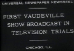
and the day was November the 2nd.1936. and inside the cramped television studio the official opening of the worlds first high
definition television service was just beginning, it was of course the start of the "B.B.C. television service"
Although Baird was
very popular in the press of the time he was less than popular amongst a large portion of the scientific "ELITE" he was ,
they thought more an entrepreneur than a scientist and unable to accept that although he was the first to demonstrate any
form of real television it was a mechanical system of very limited usefulness. It was considered that the mechanical system
had reached the end of its development at a stage where the electronic systems were just beginning.
During
the period prior to the start of the television service the rivalry between the protagonists of the two systems was so great
that the governments television advisory committee had recommended that the B.B.C. trial both systems on an alternating weekly
basis starting on November 2nd for a period of three months. Prior to the trial run the post office and B.B.C. engineers were
already quite nervous about the reliability of the Baird system and intervened when it was decided that the Baird system would
be the system employed for the first week. The decision was made by tossing a coin , the most impartial method the controller
of the B.B.C. could think of at the time.
To overcome the
engineers fears of the Baird system breaking down during the opening ceremony it was decided to repeat the opening again that
same evening employing the M/E.M.I. electronic system, this is in fact what happened, both systems operated quite well but
it was thought that although the M/E.M.I. system produced the better result the engineers thought that they had seen even
better results from the electronic system during the trials prior to the official opening.
It is pertinent
at this point to detail the two systems being evaluated:-
Baird
Marconi/E.M.I.
lines
240
405
vertical rate 25 scans per second
50 scans per second
scan system sequential
interlaced*
video bandwidth 2Mhz.
3Mhz.
scan type mechanical
*
electronic
camera type flying spot / disk*
Emitron camera tube
tx power
15KW pk white
17KW pk white
picture carrier 45MHz.
45MHz.
sound carrier 41.5MHz.
41.5MHz.
aspect ratio 4:3
5:4
*Baird was experimenting at this time with an all electronic "Farnsworth
image dissector" however it was not suitable as a live studio pickup camera due to it's poor sensitivity despite being fitted
with an integral electron multiplier.
*The flying spot scanner was a modified type of "Nipkow disk" operating
in a vacuum" a similar system was employed in the various film scanners.
*Interlaced refers to a method of flicker reduction and bandwidth conservation
employed in scanning television systems that was patented by Ballard of R.C.A. during the late 1920's. The original patent
referred in particular to mechanical scanning but was equally applicable to electronic scanning.
From
the above table it can clearly be seen that the M/E.M.I. specification beat the Baird system by a comfortable margin, that
however is not to say that in reality either system operated to the best of its ability, what we can say is that even if the
Baird system produced the best picture the system was capable of, the M/E.M.I. was able to equal it long before the system
had reached its maximum realizable capability.
From the tests
conducted during the initial period up to xmas of 1936 it became overwhelmingly clear that based on reliability alone the
electronic system was far superior, the mechanical system suffering from almost daily breakdowns whilst the other system was
gaining the reputation of being quite reliable despite a couple of faults that put the station off the air for up to an hour.
One of the
problems that plagued the Baird system was the system employed to televise studio productions, it was the intermediate film
process whereby the programme was shot on film rapidly developed and dried then scanned by a mechanical scanner, this caused
a sound delay of around a minute or so so the sound was recorded on the same film to overcome the problem and in so doing
created another problem that of very poor sound quality at times it was reported that music was little better than horrendous
in quality and speech barely intelligible. A major advantage of the electronic system was the hitherto unheard excellence
of sound quality made possible by the use of the V.H.F. sound carrier and the ease of obtaining 15KHz. bandwidth both in the
transmitter and in the receiver.
Going back to the problems
of the mechanical system using film one must realize also that the frequent film breakage's that occurred did little to enhance
its reputation with the production staff. A major problem with the film system that did not relate to reliability was that
of inflexibility in production, the camera because of its being tethered to what amounted to a complete film developing, fixing
and drying equipment was limited in the amount of movement available to the producer in fact all that was available was limited
pan and tilt dollying, in and out was impossible the best that the producer had was a slow lens change. The most dramatic
disadvantage however was the delay between shooting and previewing, one had to wait for about a minute after calling the shot
to seeing if it worked and if it didn't what was one to do about it , try another shot and wait another minute ? quite a few
performers refused to be televised by the Baird system and the producers Cecil Madden in particular hated the weeks when the
Baird system was being used, he described it this way " when using Mr. Bairds equipment it was as if we were trying to produce
a programme live to air with equipment that was still in the experimental stage and still being experimented with, we had
no confidence in the gear whatsoever and could never predict what the outcome might be.....
Feedback to the B.B.C. and the Television advisory committee under the chairmanship of Lord Selsdon was considerable,
however not all of it was accurate or for that matter unbiased. The Cossor company , a producer of radios and radiograms before
W.W.2. had a very high reputation in the industry and spent quite large sums of money on research and development not only
on radio but also on television and oscillography, held numerous related patents and boasted such eminent engineers as Puckle
who was responsible for timebase designs that were employed right up to the end of the valve (tube) era, the companies input
was very valuable not only because of the foregoing but also because it had no financial interest with either of the companies
tendering for the supply of their system and related equipment to the B.B.C.
In a letter to the head of the
B.B.C. Mssrs Cossor proffered the following observations:-
In our humble opinion the Baird system has the following defects, the film scanning disk appears to have been manufactured
with unequally spaced holes, the result being that any vertical picture element being televised appears on the televisor screen
ragged, this problem is constant and reduces considerably the maximum resolution inherent in the system. The holes in the
scanning disk from time to time become blocked and cause black lines to appear across the picture.
Continuing with their observations Cossors ask when the black level will conform to the published standard of 40% of the available
signal instead of 50 to 60% that they are presently transmitting , the result is a lack of picture contrast, added to
this they "Bairds" do not transmit the correct vertical masking signal thereby reducing the number of active picture lines
so much that it is debatable if they are in fact transmitting high definition television
( more than 200 lines) . They then continue " we would also be interested to know if and when they will begin transmitting
rectangular line synchronising impulses, at present they transmit impulses whose trailing edges are exponential rather than
square, this causes horizontal displacement of the picture on some makes of televisor", Cossors went on to mention that "our
receivers however do not suffer from this problem".
In contrast to the disastrous report on the Baird system the M/E.M.I. transmissions fared very much better Cossors report
goes on to mention that "the transmitted wave conforms in every detail according to specification unlike the Baird system
and the Emitron cameras seem to be most versatile giving the producers a most useful and creative tool for this new
media, the pictures seem to be consistently as good as one could wish for. There where a couple of points however that should
be mentioned and they are that from time to time the M/E.M.I. pictures appeared to have excessive high frequency response
causing an unnatural appearance to the picture edges and the other defect is that some kind of low frequency distortion seems
evident and causes a change in picture brightness following bright objects such as white graphics or text, the problem
though is minor and we have no doubt that as the art of television progresses these minor problems will be remedied, they
will any case go unnoticed by all but the most fastidious critic.
By mid December it was becoming apparent that little or no contest existed between the two systems of television being trialed
at Alexandra Palace, the Baird equipment was proving less and less reliable and the time being put in by Bairds technical
staff was increasing, due to lack of experienced engineers those who were keeping the ship afloat were becoming less and less
effective and and some rapidly losing their motivation due to over work and lack of sleep.
One of the problems that reared it's ugly face after a short period of time was the difficulty experienced in keeping the
scanning disks "running true" indeed it must be remembered that the disks were being operated at a rotational speed of 6000r.p.m.
albeit in a vacuum to reduce air loading and no doubt primarily to reduce the chance of the scanning holes becoming blocked
with dust etc. Operating in vacuo however did not prevent rapid wear on the shaft bearings or whatever it was that caused
troublesome picture instability all we do know is that the records show that the problem increased in frequency and
severity.
By early January
1937 it became obvious that no further appraisal was needed M-E.M.I. were the victors and the Baird transmissions ceased
at the end of January, it was a timely and non traumatic end of the mechanical t.v.era.
One thing that did come out of the trial was how close the apparent picture quality was between the two systems when everything
was going well in the Baird studio. During a demonstration for the press and the trade just prior to the official opening
of the service in November a number of technical critics pointed out that due to limitations in the receiving equipment it
was difficult to see any difference between the 405 and the 240 line systems, in fact a critic from the radio manufacturing
organization thought that the performance of the Baird film scanning equipment was better than the M/E.M.I. film scanner
with it's emitron camera tube, it is doubtful though if the same film footage was used in both tests so it is difficult to
know how valid the comparison was, we must also remember that there would have been quite a few hours between tests so that
direct comparison was impossible, even so it is still interesting to note the comparison.
One of the somewhat
strange things to emerge from the test period is the lack of comment regarding the flicker that must have been observed on
the Baird transmissions due to the 25Hz. vertical scanning rate, it should also be stated that the horizontal scan rate was
6000Hz. as opposed to the M-E.M.I. system of 10125 Hz. In other words the scanning beam in the Baird system had almost
twice the time to excite the phosphor on the display cathode ray tube, the result being a brighter picture, it may be reliably
demonstrated that the brighter the picture the greater the observed flicker. To be fair there was some comment but very little
from the less technical critics, it should also be remembered that M-E.M.I. chose 50Hz. as their vertical rate to avoid the
flicker problem even though it meant employing a non E.M.I. patent, it being held by R.C.A. and patented by Ballard. Sir Isaac
Schoenberg head of E.M.I research said "had there been any way to achieve interlaced scanning without using the Ballard patent
I would have known and used it". That was over sixty years ago and since then nothing has changed.
It is easy today for us to look back at the nineteen thirties and wonder why the television advisory committee even considered
giving the 240 line Baird system a trial after all it was competing against a system that offered almost twice as many lines
and twice the vertical scanning rate. The choice now seems obvious but then the choice was not so easy for the
following reasons:-
The decision to try both
systems came about because of lack of confidence in the M-E.M.I. offering, that of 405 lines. At the time of the offer we
are well reminded that the system was barely out of the experimental stage, Schoenbergs decision to go for such a system was
made only a few weeks earlier following a proposal by Allan Blumlein in late March 1935, he (Blumlein) considered that to
provide a system significantly better than Bairds the definition needed to be at least half again as good i.e about 360 lines.
It must also be remembered that Schoenberg had decided that interlaced scanning was to be employed with a 50HZ. vert
scan rate, to achieve this the vertical and horizontal scan rates had to be phase and frequency related to obtain interlacing.
Using the Ballard system of
interlacing the total number of lines has to be an odd number i.e. 243 lines or 405 lines, now to phase lock both scan generators
they must each derive their frequency from a common source, a typical system is as follows, a master oscillator operates at
twice the horizontal scan rate and divided by two to provide horizontal frequency, the master is also divided numerically
by an amount equal to the number of lines to be scanned this results in the vertical scanning rate, to prove the point here
is an example. For a 625 line system we employ a master oscillator operating at a frequency of 31250HZ. this we divide by
two to obtain 15625 HZ. to provide our vertical rate we divide 31250 by 625 and of course the result is 50HZ.
The trick is to divide electrically by 625 and in this instance we can divide by five four times (31250 /5=6250/5=1250/5=250/5=50).
To divide large
odd numbers by large amounts the odd number is best chosen by deriving it from a multiple of small integers rather than
trying to divide it by a large amount i.e to electrically devide by 27 it is easier to devide by 3 three times than to attempt
a direct division 27 (at least it was until the introduction of digital techniques some thirty years later in the nineteen
sixties) so the choice of the number of lines for a television system employing interlaced scanning was limited to the extent
that permitted easy pulse generation timing through electronic division , let us look at a few examples.
5*5*5=125
3*3*3*3*3=243
7*7*7=343
3*3*3*3*5=405
7*5*5*3=525
5*5*5*5=625
The last three examples are of course familiar to you and are the division
ratios that were used in sync pulse generators in the early days of television, we must not loose sight of the fact that what
ever the number of lines chosen the vertical scan rate was always the same as the powerline frequency, this avoided a beat
being set up between the vertical frequency and the powerline frequency and distorting the picture due to unwanted interactions,
an example being caused by less than perfect h.t. filtering in the receiver feeding the vertical scan generator,
if the vertical scan rate was 48Hz. per second and the power line was 50 HZ. per second the picture would possibly expand
and contract to some extent at the rate of twice per second. The example just given used to occur when t.v. receivers
were operated from non synchronous power generating plants and the generator frequency changed with load or were not set up
for the correct frequency.
It would appear that the choice of 405 lines was made because the lower choice of 343 lines was being demonstrated at the
time in the R.C.A. laboratory in America and Blumlein and Schoenberg did not want it said that they were just copying the
Americans, this is not the opinion of the writer but recollections made by a number of Blumleins co workers a number of years
after his death and should be treated as hearsay rather than a definitive statement, however it certainly does seem credible.
The offer by M-E.M.I. to supply a 405 line system came as quite a shock to the T.A.C. and also to most of Schoenbergs research
team, of the latter there was considerable doubt if the system could be made to operate it the time permitted by the T.A.C.
(The system was to be operational by the end of 1936). Blumlein and his co workers had demonstrated the 405 line system in
the laboratory and demonstrated its superiority over the 240 line system but that was a far cry from actually transmitting
and receiving it on ultra short wave (7 metres - 45MHz.) with the unheard of bandwidth of nearly 3 MHz. Prior to April 1935
the maximum bandwidth achieved had been of the order of 1.25MHz. sufficient for the 180 line experimental tests carried out
by Baird and M-E.M.I. The new system not only required very wide bandwidth but also came with the added burden of a
fivefold degradation of the system noise figure, however it did permit future improvements to be made as and when technology
permitted without changing the system parameters, thus removing the need to modify existing receivers or making them obsolete.
Isaac Schoenberg had promised that using his system two types of receivers were possible , one employing the full bandwidth
of 2.7 MHz. and producing very fine picture detail and the other type using perhaps 1MHz. bandwidth and showing only about
one third of the detail although said Schoenberg "the pictures would still be quite acceptable in fact jolly good". The cathode
ray tubes of the day operated at between 2.5Kv and 4Kv, were mostly electrostaticaly deflected and had only just sufficient
vacuum, needless to say the spot size achieved was not very small or bright so it is doubtful if many receivers of the day
could do justice to the full bandwidth transmitted.
When the service was first introduced the average screen size was 12inches measured diagonally Bairds marketed a 15inch receiver
possibly manufactured by Bush Radio and Cossors produced a 10 inch receiver. All sets at this time included sound but some
later small screen economy receivers only provided low level audio output for connection to the pick-up terminals of the household
radio, thus reducing the cost of the television receiver.
By the end of 1936, some two months after the inauguration of the B.B.C. television service the radio manufacturers had supplied
approximately two thousand t.v. receivers to the trade of which only half had been sold to the public, however
those remaining in dealers premises were usually on display in shop windows and during the evenings drew significant crowds
to marvel at the latest scientific wonder. During the summer months and during afternoons the receivers could not be demonstrated
due to the daylight obliterating the rather dim pictures, during these times it was necessary to demonstrate the receivers
in subdued lighting, public viewing from the streets was thus prevented.
During the year of 1937 the London public had their first opportunity to sample the outside broadcast and took to it like
fish to water, their first offering being the coronation of King George the sixth during May of that year. the B.B.C. having
taken delivery of a three camera O.B. van only a short time before and although the cameras were not allowed inside Westminster
Abbey they did cover outside scenes remarkably well and captured some excellent close-ups that included one of the King waving
to the camera from the State Coach as it passed the camera position on its way from Buckingham Palace to the Abbey.
Later during that same year viewers were able to see live theatre, football, tennis, (the Davis cup) from Wimbledon
and the Armistice service from the Cenotaph, all the time the number of receivers in the hands of the public continued to
increase albeit at first rather slowly.
The year 1937 must have been rather depressing for John Logie Baird, the television system he developed in the mid 1920's
was just not up to the job demanded of a system that would be acceptable to the general public. It is to the credit of Baird
and his helpers that they managed to cobble together a working system at all, despite all of its shortcomings and severely
hampered by it's terrible lack of versatility the system did provide basic and at times good results within the confines of
it's parameters.
The
Baird system of television even using the Farnsworth pick up tube could never compete with E.M.I.'s Emitron for the simple
reason that the basic theory of operation of the Farnswoth tube relied upon instantaneous photo emission, that is to say that
any one part of the image falling on the photosensitive target in the tube contributed to the video signal only during the
time that it was actively scanned whereas in the E.M.I. tube the principle of photostorage was employed wherein the entire
phototarget formed upon it's surface a charge whose area was charged in proportion to the light falling upon it and each area
discharged as the scanning electron beam was swept over it. A little thought will soon reveal that the E.M.I. tube has the
time of and entire vertical scan period form a charge on its phototarget whereas the Farnsworth tube contributes nothing during
this period, this statement in reality is an oversimplification, however even despite the fact that the E.M.I. tube provided
only five percent of the theoretical video signal due to secondary emission effects it was still many times more efficient
than the Farnsworth image dissector.
Perhaps one of the most important shortcomings of the Baird system was the simple fact that using any of their mechanical
scanning systems for programme pickup it was in the nineteen thirties totally impossible to mix two video sources together
for the purpose of special effects no matter how simple because there was no method available then to remove the timebase
errors that would have caused horizontal jitter or worse if the phase of a mechanical disk was compared with another disk
or an electronic camera. It could be argued that one could genlock the electronic camera to the mechanical scanner , but it
is most unlikely if such a crude system would have been acceptable to the B.B.C. and even if it were it would not have been
possible to genlock two mechanical scanners horizontally due to the problems of inertia that caused the problem in the first
place.
What one might ask if the Baird had discarded the mechanical system entirely and concentrated entirely on the Farnsworth camera
would he have been in a better position as a rival to M-E.M.I. ? most likely not because to compete against them would have
meant employing the Ballard patent for interlacing if they had intended going for 405 lines 50 scans per second, one can hardly
imagine R.C.A. the holders of the patent allowing Bairds to use it as they (R.C.A.) were shareholders in the M-E.M.I. company.
It should also be made clear that Bairds held no significant patents that dealt with electronic television either on the transmit
or receive side so that to produce a comparable system to M-E.M.I.'s would have meant employing many of their patents, it
does not need much imagination to conclude that Isaac Schoenberg would have declined Baird permission.
It goes without saying that an electronic system operating on a 240 line sequential system with a 25Hz. vertical scan rate
would have been out of the question if only from the flicker standpoint having once made a comparison with a 50Hz. system,
at least that is the opinion of the author.
Why Baird continued for so long with a mechanic system is difficult to say, perhaps he lacked the full understanding of electronics
that were necessary to implement such a method, if that was the case one must question why those people working with him did
not realise the failing and moreso it's inevitable disastrous consequences for the Baird Television Company and report it
to the board of directors.
Baird did not control the Baird Television Company it's majority shareholders being the Ostrer brothers who also controlled
Bush Radio a British radio manufacturer who incidentally manufactured a number of low definition receivers for his 30 line
system back in the early thirties.
Perhaps those working with Baird did not have the courage to challenge him due to his high reputation amongst the not so well
informed but very influential press of the day who paraded Baird as a national hero. One must also consider the possibility
that Baird's co workers did not want to be the ones to cause him to topple from his pedestal better perhaps let the B.B.C.
the G.P.O. the T.A.C. or even the public for that matter be the judges, that way their loyalty to Baird could not be questioned,
in some minds whether right or wrong an issue of the gravest importance.
If the past two paragraphs are both wrong in their suggestions it still seems almost impossible to believe that some at least
of Bairds assistants and co workers would not have been well enough versed in the state of the art to have realised that mechanical
television had no future, they must have had a very in-depth understanding of the subject to make Bairds system work as well
as it did. G.E.C. for example had a very close liaison with Baird et al as suppliers of cathode ray tubes and transmitting
valves from time to time. Mullards also supplied quite a lot of time and assistance to the Baird development team with early
ultra short wave transmitter design and the supply of output and modulator valves, perhaps Bairds word carried more sway than
their technical know how, sixty four years after the event who knows? like so many events in history our postulation can be
little more than circumstantial and or educated supposition.
And the rest of the world.
It would be wrong to believe that the rest
of the world sat watching the British develop television and did no research them selves. Germany in fact started
a television service of sorts themselves in Berlin in the spring of 1936, broadcasting from to a number of "Fernseh Halle"
or television halls using iconoscope cameras made by Telefunken and using 180 lines non-interlaced scanning with 25 pictures
per second. It was not possible in Nazi Germany at that time for the public to purchase television receivers that was the
reason for the halls. The Olympic games in Berlin were also covered and it is interesting to note that Walter Bruch was a
cameraman at the games, Bruch was of course the inventor of the P.A.L. system in the early sixties. It has been argued in
the past that credit should be given to the Germans for being the first regular television broadcasters in the world, well
this would be hard to substantiate as Baird with the B.B.C. began to broadcast tv in the late 1920's albeit with only 30 lines.
The B.B.C. claim to have started the first regular high definition tv broadcasting service on November 2nd. 1936, high definition
then meaning more than 240 lines and this claim has never been challenged because the claim is in every respect correct.
The Russians were a little behind the "8 Ball' testing a 30 line system in the late thirties on the broadcast band, they called
their system "Radio Vision" but was very short lived, that they should have been so far behind in t.v. development is suprising
given that Schoenberg and Zworykin were both emigre Russians. It is possible that the political system of the time would not
fund t.v. research due to more pressing priorities.
The Americans were as advanced as the British in many aspects of electronic television but doubted its commercial viability
in the late thirties. The system in the United States differed from the British system of broadcasting in that in Britain
radio and tv funding was entirely derived from license fees and grants from the treasury granted by the chancellor of the
exchequer, the broadcasts carried no form of advertising or sponsorship and was to remain that way until well after W.W.2.
The American system was not of the public type but relied entirely upon advertising and commercial sponsorship for its existence,
such a new technology as television would initially require massive funding with a long wait for profitable returns,at least
so the brokers believed. Television was not to begin in America until 1939 with the opening of the World Fair in New York,
with a system of 441 lines interlaced, and a vertical scan rate of 60Hz. and 30 pictures per second. The pickup tube
used in the cameras was naturally Zworykin Iconoscope and manufactured by R.C.A. Farnswoth's image dissector tube was never
used for the reasons outlined earlier.
By 1939 both the French and the Germans had begun transmitting 441 line 50hz. interlaced t.v. using iconoscope type tubes,
all transmissions being on the low V.H.F. channels, The French were transmitting from the Eiffel Tower and the Germans from
the Witzleben tower near Berlin.
By 1939 we see that in Europe and the U.K. there were still only three countries seriously involved in t.v. and of these only
The U.K. had a reasonably sized audience it had grown to about 80,000 if we presume four viewers to each set and there
were known to have been 20,000 tv licenses issued that year, perhaps due to the uniqueness of tv at the time the number of
viewers may have been larger say six per set but it is doubtful if the number was less than four so the figure of 80,000 should
be considered realistic.
By late 1937
the B.B.C. had embraced the use of the "Super Emitron" camera tube developed by Lubsyznski at E.M.I's research facilities
at Hayes Middlesex. The tube had vastly improved light sensitivity and naturally provided better pictures under overcast or
poorly illuminated conditions
Up until September 1939 it had been the plan of the government to extend the coverage of British television to the major population
centres of the nation starting with Birmingham in the early 40's, that plan however had to be postponed due to an arrangement
between Herr Hitler and Neville Chamberlain,Need any more be said? The writer believes only this: British television up until
that time was may far the most advanced in the world in production technique,technical performance, versatility, and viewing
audience. The entire system was unceremoniously switched off at the start of the war and was not to return until the summer
of 1946 with the same 405 line standard that was to remain until 1986 essentially the only major parameter change was the
aspect ratio, it was changed from 5:4 to 4:3 in the late forties. The 405 line system of Isaac Schoenberg, A.D. Blumlein and
the entire design team of M-E.M.I. operated in the U/K for a total of nearly forty three years, bringing to the people of
the British Isles Two Coronations,royal weddings, Sir Winston Churchill's Funeral, The assassination of President Kennedy,
numerous Olympiads, the beginning of commercial television, Britain's first Lady priminister, the Landing on the Moon by the
Americans, the Beatles, Panorama , The Vietnam War, the start of satellite television relaying, Casius Clay, The cold
war, the first heart transplant by Christian Barnard in South Africa, That was the week that was, the wonderful commentaries
of Richard Dimbleby, Monty Python and who will forget Coronation St. Emergency Ward Ten, Steptoe and Son, What's My line Muffin
the mule Cafe Continental, Dixson of Dock Green and so many more wonderfully British t.v. programmes,( YES PROGRAMME was spelt
that way and still is by many English speaking people) too many to mention in this little narrative, but a wonderful collection
of memories they are, to be handed down to future generations both in the form of the spoken word and a fine collection of
film recordings and video tapes.
I think J.L.Baird and I. Schoenberg would be justifiably proud of their achievements and progressive vision if
they were alive to-day, it is sad to note that despite J.L.Bairds initial foray into television and his many firsts including
transatlantic television, nocturnal television, colour television, telerecording and outside broadcasting, none of the methods
used were used in the television of M-E.M.I. or used at any time since for use in television broadcasting.
The system of television devised by M-E.M.I. is the basically the same as that employed to-day, the monochrome part of the
signal is virtually identical the differences being the use of equalizing pulses before and after the vertical sync train
and of course the number of lines, the later however is more a change of standards than a change of system as is the change
from positive to negative modulation for vision ( the French still employ positive modulation and for that matter a.m. sound).
Colour is only additional luggage carried along by the basic transporter.
To-day we
are seeing the emergence of digital television and with it a whole new technology that is rapidly developing at a growth rate
undreamed of a few decades ago fired however by the same driving force that was at work back in the 1930's" mankind's imagination"
A few details
about the t.v. receivers in use before W.W.2. might be in order at this stage, the first batch of sets developed for the start
of the television service were dual standard types to cater for both systems then in operation. The screen sizes were about
twelve inches diagonally and masked to produce either a 4:3 or 5:4 aspect ratio according to the manufacturer, as stated earlier
Baird used 4:3 whilst M-E.M.I. 5:3. For some obscure reason Bairds scanned the picture from right to left whilst M-E.M.I.
chose to scan from left to right a minor detail perhaps but it did necessitate reversing the horizontal deflection plates
or scanning coil connections between systems and with electrostatic picture tubes this entailed switching a high impedance
circuit producing 1200vpp. or so, not so practical in a piece of domestic equipment in those days paxolin insulated switches(ceramic
types were considered too expensive by some makers).
Some sets produced in 1936 employed
electrostatic tubes with a very low scanning angle the latter to reduce the required deflection voltage, the tubes were so
long that many were mounted vertically , that is with screen pointing upwards and a mirror was mounted in the lid of the cabinet
in such a manner that when the receiver was in use the lid was hinged up to an angle of forty five degrees and the mirror
reflected the image for viewing in the normal fashion, the H.M.V.901 model was a typical example, although the tube
in this set was in fact magnetically deflected. In contrast to the simpler method of scanning i.e. electrostatic as employed
by G.E.C. for example, it is an enormous credit to Bairds that from the start they chose to use magnetic deflection and a
glance at their circuitry reveals a true mastery of the art, it pre-dates Blumleins patent on magnetic deflection employing
flyback energy recovery of 1937., perhaps the design originated in the Bush Radio laboratories but that does not lessen the
credit due to Bairds for accepting and marketing the system, it is perhaps one of the few things that they did that that is
still with us to-day.
Receiving
techniques at the time were really quite primitive by the standards in use a decade later, due mainly to the fact that there
had been no demand for high Mu valves (tubes) with low input and output capacitances prior to the start of the television
service, such valves are required in order to provide reasonable gain bandwidth products required in the receiver r.f.and
i.f amplifiers as well as the video frequency amplifiers. All circuitry was therefore new and untried employing new valve
types along with resistors and capacitors and valve bases designed primarily for domestic radio use.
A few sets employed t.r.f.
designs with very limited gain the remaining sets used the superhetrodyne principle one r.f. stage , a mixer and an i.f. amplifier
system operating as low as 7MHz. reading the literature of the day and later reminiscences it seems that stability was
a nightmare and full bandwidth almost unheard of.
Despite the fact that the t.v.
transmitter at Alexandra Palace employed double sidebands (and continued to until the end of its use in the 1950's) it was
not uncommon for receivers to employ vestigial sideband techniques, not for the reason we use it to-day but as an aid to sound
rejection in the vision channel and to obtain higher gain per stage, the upper vision sideband was employed which was farthest
removed from the sound carrier.
The writer had in his
possession in the late 50's a 7inch H.M.V. receiver and remembers well the very good pictures it produced at Chingford following
the replacement of all the paper capacitors and most of the electrolytic types, it appeared that most of the valves in the
t.v.section were original, he also recalls rewinding the vertical deflection yoke assembly, it was quite quite separate from
the horizontal coils and was manufactured in mid 1939. The set also was equipped with a very good radio, the t.v. was set
up for vestigial sideband reception as mentioned earlier but with the closure of A/P the receiver was re-aligned for lower
sideband operation and a sound trap fitted, the alignment was carried out by eye, the writer at that time owned no test equipment
other than a continuity tester employing a buzzer, a 50uA meter movement and a handful of resistors used as shunts or multipliers,
a neon lamp and a pair of s.g. brown headphones, also very little money but lots of enthusiasm.
The cathode ray tubes before the war were not aluminized and suffered from ion burns at the centre of the screen, they also
operated at rather low levels of e.h.t. and produced very dim pictures by to-day's standards. Had the tubes been aluminized
there would have been no ion burns but the pictures would have been much dimmer if operated at the same e.h.t. as the non
aluminized tubes, the e.h.t. needs to be at least 5Kv. before light the output from both tubes is equal and not
until it is about 7.5Kv. does the aluminized tube begin to show a marked advantage.
Producing voltages much higher than about
5Kv. was both difficult and undesirable as it was derived by stepup transformer from the mains in the first place and imposed
horrendous insulation problems as well as safety concerns and secondly as the e.h.t. supplied to the final anode of the c.r.t.
is increased the scanning demands become increased to the point of being impractical for electrostatic tubes and in the case
magnetic tubes the horizontal scanning power was unobtainable there being no ferrites or the like with which to construct
deflection yokes, eddy current losses were a major problem at the line scanning frequency (10125HZ.) not only for the deflection
yokes but also for the horizontal output transformer.
Focusing was not what it is to-day, now the t.v.receiver is focused during manufacture and seldom requires further adjustment
for years if at all. In the early days of television the viewer would switch on the receiver fifteen minutes or so prior
to the start of viewing in order for the set to warm up, this meant time for the sum of the anode currents to
stabilize in order for the h.t. supply to stop drifting, this was essential as the focusing field for magnetic tubes was developed
by using an electro magnet and as the h.t. voltage varied due to load current changes so also did the focus. With electrostaticaly
deflected tubes the problem was not as severe because the focusing potential was derived from and related to the e.h.t. supply
, the focus voltage always remained a fixed percentage of the final anode voltage for optimum focus this meant that if the
e.h.t. supply varied so also did the focusing voltage thus maintaining focus, perfect tracking in practice was seldom
achieved because the focus potential was derived from a resistive divider network several fixed resistors of the carbon composition
type were employed along with a carbon potentiometer and as the components warmed up they often exhibited different temperature
coefficients and of course focus drift. Due to the focus supply circuitry operating at very high voltages(typically around
30% of the e.h.t. supply ) wirewound components were not practical because obtaining w.w. resistors with values in the megohm
was not economically possible or considered necessary.
Finally one needs
to remember that the focusing field either magnetic or electrostatic for a cathode ray tube becomes increasingly diminished
as the e.h.t. value drops this in turn also means for a c.r.t. operating at a very low value of e.h.t. the focusing field
is also very low and means that for a given drift in absolute values of the focusing field either volts or gauss the tube
operated with a high value of e.h.t. will suffer a lower amount of defocusing compared to that of a tube operating at say
half the e.h.t. supply.
Permanent magnet focusing was
employed by Cossors just prior to the war and vernier focus was obtained by varying the e.h.t. the method used was to
have a 100K ohm pot wired in series with the cold end of the e.h.t. transformer secondary !!!, it worked rather well but the
focus drifted even moreso because the main focus field was now fixed and variations of e.h.t. due to mains fluctuations etc.
could not be easily compensated , one Cossor receiver employed a hybrid arrangement of permanent magnets bucked
by a focusing coil this reduced the power consumed by the coil and afforded a system of drift cancellation that worked very
well when set up correctly. All sets had a customer operatable focus control often placed on the front control panel along
with "brilliancy" "sound" and "contrast".
An interesting thought, how
troublesome would the early sets have been when operating on the 240 line system with a line rate of 6KHz.? and using magnetic
deflection, by trouble one refers to the whistle emitted from the deflection yoke and the output transformer , it was bad
enough with 405 lines
MORE TO FOLLOW ON THE ABOVE SUBJECT .


Above left E.M.I. studio Emitron camera, middle Cossor t.v. right Murphy
9" t.v. All produced before W.W.2. in the U/K. for 405 line operation. More to follow later.
Now for something a little different.


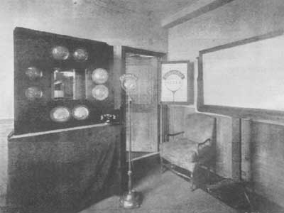
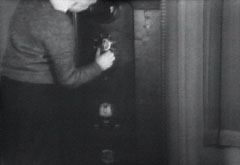
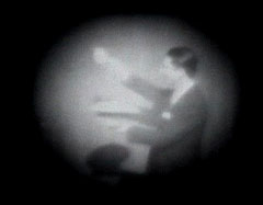
Above left Adele Dixon off screen photo, centre reproduction 1939 type
tv built and designed by Barker using all pre 1939 parts, right, tuning signal off screen photo. Both off screen photos taken
from t.v. in centre, the receiver uses a triode Emiscope Tube with a 10inch diameter screen. The tube operates from a mains
derived E.H.T. supply of 4900 volts and employs electromagnetic focusing and deflection.
The design of the receiver above was undertaken with the view in mind of replicating as far possible a t.v. that
could have been built prior to W.W.2. with the knowledge and circuit practice then in common use. The design however does
as far as possible use the latest types of valves that were being manufactured around September 1939 and includes a large
number of EF50s, they were first produced by Mullards in February of that year with a slightly different shape of pins and
soon after changed to the standard type pins used throughout the war and after until about 1950 when the EF91 and EF80 took
their place. The EF50s are used as follows:
Common R.F. Amp, local Osc, mixer, common I.F. 2nd. and 3rd. vision
I.F.s 2nd. sound I.F. Video amplifier and sync separator. Paxolin valve holders are used. The sound system
follows using an EBC33 for demod and 1st. audio amp followed by a 6V6 output stage. The video demod uses an EA51 and the vertical
osc and horizontal osc employ a 6N7 (half for each function) each stage being a blocking oscillator with a 6V6 as vertical
output and an 807 as horizontal output. Direct triggering from differentiated horizontal sync is employed rather than flywheel
sync to lock the horizontal timebase as was the norm at that time and integrated frame sync is used to lock the vertical
timebase, both systems being entirely adequate. For E.H.T. a 2X2 valve is used and for H.T. a 5U4 is used, no energy reclaim
diode is used in the horizontal output stage although the system was certainly employed by some manufacturers, instead
use was made of critical damping and as can be seen in the pictures above the results are acceptable as evidenced by the linearity
of the tuning signal.
The receiver is a double sideband superhet with the vision if centered 13 MHz. and the sound I.F. at 16.5MHz. these frequencies
minimise patterning from harmonics of the vision I.F. falling in the region of the 45MHz. the vision receive frequency. No
sound or vision interference limiters are employed although a white spotter would be helpful and may be added in the future
again such refinements were used in the more expensive sets. The amplified video signal is applied to the cathode of the c.r.t.
via an anti-flutter network that serves two functions: firstly to reduce the amount of d.c. appearing between the heater and
cathode of the tube and secondly to reduce the effect of aircraft flutter caused by a rapidly changing received signal level
as experienced when signals are received from flying aircraft as well as the direct signal, as the phase of the two signals
vary in phase relative to each other due to the varying path length of the reflected signal the sum of the combined signals
either increases or decreases according to their phase relationship and either brightens or darkens the picture. the reduction
of observed flutter is about 50% whilst about 30% of the d.c. picture component is lost, this effect is not noticed
by most viewers.
A most useful by product of driving the c.r.t. cathode is that the composite video signal at the anode of the video amplifier
is of negative going picture polarity, that also implies positive going synchronising pulses and makes synch separation very
easy. the signal of about 45v.p.p. is a.c. coupled to the grid of a pentode valve operating with a very short grid base, the
grid is driven into grid current by the sync pulses and for the duration of the active line the valve is cut off thus anode
current only flows during sync period thus effectively separating the sync from the video. Negative going sync appears at
the anode of the sync separator valve across a fairly low value anode load in order to preserve the fast leading and trailing
edges of the pulses. The circuitry just described continued to be used until the end of the valve era around the late 1960's
with only minor differences by all major set manufacturers throughout the world for the reasons just outlined.
The vertical timebase generator employs a blocking oscillator, the sawtooth voltage being taken from the anode circuit
and capacitively coupled to the control grid of the output beam tetrode, no output transformer is employed, instead r/c coupling
is used to couple to a high impedance deflection yoke (900 Ohms) the coupling element being a 50uF electrolytic capacitor
and the anode load resistor has a value of 5.6K Ohms, no bypassing of the cathode resistor is employed as suitably high values
of capacitance were very costly in the early days, the negative feedback introduced posed no problem as there is plenty of
drive available from the previous stage. The non linear vG/iA curve of the output valve under the bias condition used adequately
cancels the exponential charging rate of the timebase generator sawtooth forming capacitor. The resultant vertical linearity
achieved is better than 5% and is not critical of component values.
Common practice at the time we are trying to emulate to obtain E.H.T. for the picture tube was to derive it from the mains
through a step-up transformer, that is the system the writer employed, finding a suitable transformer initially posed something
of a problem until a transformer used to operate a neon advertising tube was located, it is quite small and due to the large
gap present between the outer of the secondary winding and the laminations enough space was found to wind the heater winding
for the E.H.T. rectifier and add the required insulation without removing the laminations. Filtering of the rectified
voltage was solved by employing a couple of 0.05uF paper caps rated at 7KV. that were removed from a piece of early t.v. equipment
and of similar type common in early t.v. sets, a 25MOhm bleeder resistor completed the circuit and comprised 5 5M Ohm
resistors in series across the filter caps, a 470K Ohm resistor is placed in series with the output lead to the c.r.t. for
personal safety reasons as the supply can provide a lethal shock if not series current limited.
The horizontal timebase generator is the same as the vertical generator except that the time constants have been changed to
suit the frequency employed (10125Hz.) The output stage employs a small transmitting tetrode that was very common during the
late 1930's and is operated in class A. the output is transformer coupled to the horizontal deflection yoke and a series r/c
network is connected across the secondary winding of the output transformer, again the cathode resistor is left unbypassed,
the feedback introduced reducing the effect of valve aging and drift and renders the drive amplitude far less critical, adequate
width is secured when the stage is operated from a 275 volt h.t. line. The horizontal linearity is better than 10% overall.
The
performance of the set is only marred by the now aging Emiscope cathode ray tube being rather soft on picture highlights and
some geometric distortion caused by crosstalk in the deflection yoke (scanning coils) this problem will be addressed by the
author when he gets time. The receiver is capable of displaying up to 3MHz.bandwidth and sound rejection is no problem. Sensitivity
is 50uV at 45MHz. for full modulation of the tube, this is more than adequate as at these frequencies electrical interference
would have in all but the remotest areas have precluded the use of such high sensitivity. The only compromise made in
the construction of the set is the use of mylar caps instead of paper-wax types, this does not imply a better performance
but avoids stressing the now very old valves that could have taken place had the older style capacitors been employed and
became leaky. If any one is interested in the circuit details contact Victor Barker at
About the author. Victor Barker was born in London in1942 and worked in the field of television in the U/K from 1958
until 1968 when he emigrated to Australia where he has worked in commercial television production and broadcasting as well
as engineering. Victor has a keen interest in the history of television and the renovation of old tv equipment, he has a small
collection of early British t.v. receivers that he wishes to expand in the future (any help would be appreciated and adequately
recompensed). Apart from spending his working life in the field of television Victor also holds the Amateur callsign of VK2BTV
and is a very active "A.T.V.er" on the Central Coast of N.S.W. on 70cm., 23cm and 8.3 cm. During the late 1960's he spent
a great deal of time developing circuitry for recording colour t.v. on 1 inch video tape using the Ampex "A"
format, and developed a Horizontally locked recorder with sufficient stability to playback through a T.B.C. with a 1uS window
not unlike the Ampex 7809 series but with better stability. Full bandwidth recording was employed.
Victor is
well into the writing of his first novel and enjoys playing the piano for his own amusement, he is married, has two stepchildren
and three grandchildren.
Over the years Victor has appeared on all the major t.v. networks and in the print media on matters concerning t.v. broadcasting
and allied topics, he is available for lectures in the field of early television, arrangements and details may be made via
his internet address shown below.
The writer wishes to thank Dicky Howett for bringing to his attention an
error in an earlier draft of this page wherein it had been stated that the C.P.S. Emitron had been introduced during
1937. Dicky so rightly pointed out that it was the Super Emitron that was introduced. The correction has been included in
this page. V.G.B.


 N.R.I. 3" Kit TV Green


 Farnsworth with his picture tube.


 The first live public demonstration of a Baird Television system in North America since 1932 took place in Toronto in 1996.
John Logie Baird's son, Professor Malcolm Baird, gave a short speech to commemorate the 70th anniversary of the first
public demonstration of television; grandson Iain Baird, who presently works at MZTV,was in attendance to operate the
The first live public demonstration of a Baird Television system in North America since 1932 took place in Toronto in 1996.
John Logie Baird's son, Professor Malcolm Baird, gave a short speech to commemorate the 70th anniversary of the first
public demonstration of television; grandson Iain Baird, who presently works at MZTV,was in attendance to operate the
 Mechanical systems of this period are not compatible with today's TV signals. When the MZTV Museum decided to restore this


 A Successful Attempt To See By Wireless" -- Tells how Mr. J. L.
Baird is 'now perfecting' a machine designed to transmit actual [moving] images. He had successfully demonstrated the
transmission of "shadowgraphs" by wireless earlier [in 1925]. Refer to scan below for larger close-up view.
A Successful Attempt To See By Wireless" -- Tells how Mr. J. L.
Baird is 'now perfecting' a machine designed to transmit actual [moving] images. He had successfully demonstrated the
transmission of "shadowgraphs" by wireless earlier [in 1925]. Refer to scan below for larger close-up view.


 .
.


